RV Tech · Power
The Lithium Upgrade
Going from 456 Ah to 680 Ah in a 2018.5 Winnebago View 24J — and why the deciding factor turned out to be integration rather than capacity.
Why Now
A pack failed, and asked a better question
This was not our first lithium upgrade. We had already replaced the original house batteries with a pair of BigBattery OWL MAX 2 packs — a real improvement in capacity, and a set of batteries that were nonetheless completely mute. No BMS on the bus, no cell data, nothing the Cerbo could read. Dumb batteries.
In July 2026 the second OWL failed, which halved the bank overnight. We did not know it had failed. Nothing announced it, because nothing could — a battery with no voice cannot report its own death. We worked it out later, by inference, from a bank that no longer went the distance.
That is the whole case against dumb batteries in one sentence, and it cost us a summer to learn.
It was worse than a simple loss of capacity, too. We spent weeks blaming the batteries for air-conditioning trips that turned out to be a cable problem — two entirely separate faults running at the same time, and no data anywhere to tell them apart. A pack that could talk would have separated them on day one.
So the decision in front of us was not really lead versus lithium. That question was settled years ago. It was dumb lithium versus lithium that talks — and having lived with the mute version, that turned out to be an easy call.
| Period | Configuration | Capacity |
|---|---|---|
| Through Jul 2026 | 2 × BigBattery OWL MAX 2 — lithium, but no communication | 456 Ah · 6.0 kWh |
| Jul–Aug 2026 | One pack failed; running on the survivor | 228 Ah · 3.0 kWh |
| Aug 2026 | First SFK 340ELR in service | 340 Ah · 4.4 kWh |
| Now | 2 × SFK 340ELR, paralleled | 680 Ah · 8.7 kWh |
The Metalwork
Making a big pack fit a small box
The OEM battery compartment on a 2015–2019 View or Navion will not accept a modern high-capacity lithium pack without surgery. This problem is already solved, and solved well, by the View/Navion Epoch battery guide. We followed it more or less exactly.
The short version of what it has you do:
- Square off the two rounded front corners of the compartment
- Cut the horizontal "wings" on the lower front and back walls flush
- Cut the vertical stops in the lower battery tray flush
- Take roughly ¼" off the top front edge
- Cut the battery handles flush with a multitool
- Tape every cut edge, seal the compartment underside, and fill the front gap with a high-density foam spacer
Read that guide rather than this page for the fitment. It is a genuinely good writeup and there is no reason to duplicate it badly here.
One deviation worth mentioning: we used heat-formed ABS sheet to close the box — 1/8" black rigid ABS, a single 36" × 24" sheet. A heat gun makes ABS pliable enough to bend and shape by hand, so it follows the compartment's actual contours rather than approximating them, and it holds that shape once it cools — which is exactly what the bend angles on the cardboard template are for. Then RV undercarriage tape over the top, the same finish the guide uses.
The ABS is not bonded to the tray. It lifts straight out, so this is a shaped panel rather than a permanent modification, and the compartment can be returned to standard.

Where we went our own way was the battery itself — and everything downstream of it.
The Choice
Why SFK instead of Epoch
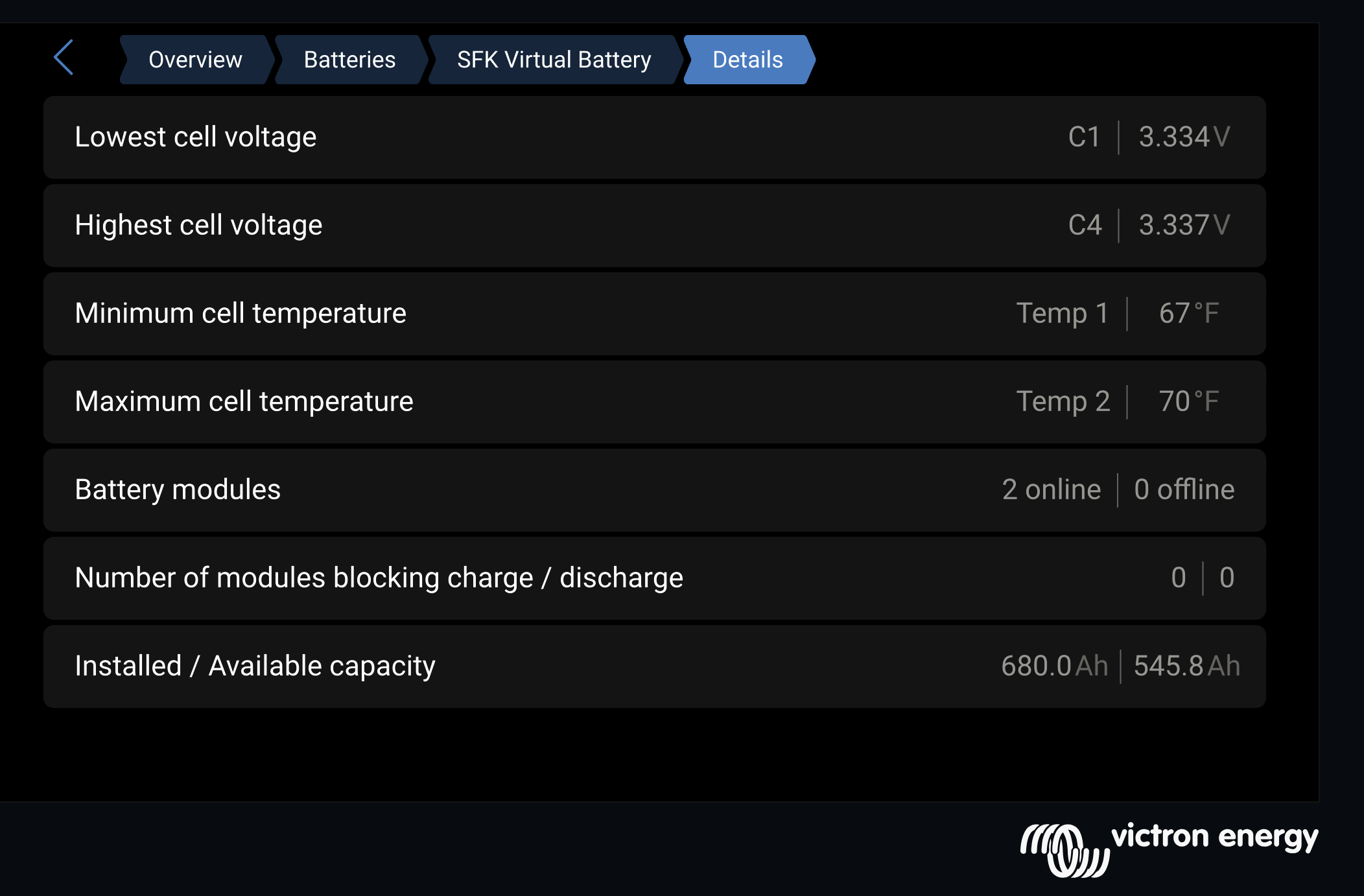
Two SFK 340ELR packs, for 680 Ah. The reason was not capacity and it was not price. It is that SFK publish a driver for Venus OS, so the batteries genuinely talk to the Cerbo rather than simply sitting in the bay being drained.
One thing a lithium conversion quietly changes is the chassis battery. It is easy to forget, because it is not the battery you are thinking about — but the maintainer that keeps it topped up from the house bank was designed around lead-acid voltage behaviour, and a LiFePO4 bank does not behave the same way. Ours is a TRIK-L-START with the diode modification that makes it work correctly against lithium. Worth sorting out before you discover it the hard way in a car park somewhere.
Having spent years on mute packs, we knew exactly what we were buying. With the OWLs, a pack could be drifting, or one cell could be quietly failing, and the system had no way to know and no way to tell us. The first sign of trouble was trouble.
The setting that was doing nothing at all
Before this upgrade, Victron's DVCC was switched on and distributing nothing — because the designated battery in the system was the BMV-712 shunt. It had to be: with dumb packs there was no BMS on the bus to nominate, so the shunt was standing in for one.
A shunt is not a BMS. It measures current in and out and infers a state of charge; it has no idea what any individual cell is doing. So the maximum charge voltage carefully configured in the system was completely inert. Nothing consumed it.
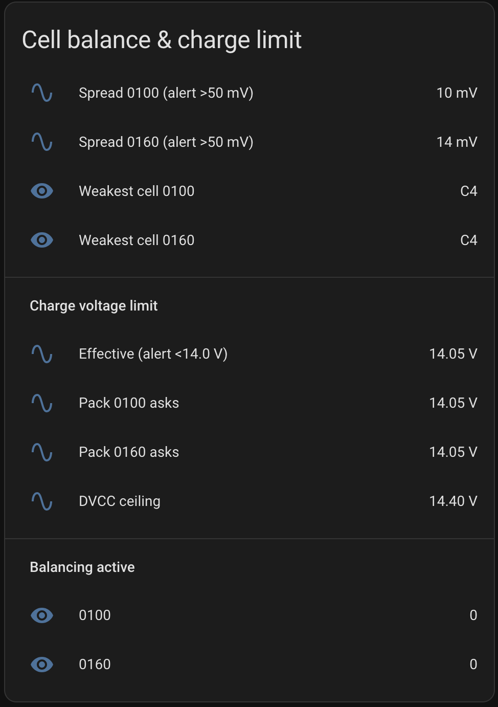
With a real BMS on the bus, the battery publishes a limit and the DVCC-controlled chargers obey it — the MultiPlus and the SmartSolar. One number, set in one place, respected by both.
With one exception worth being precise about. Our DC-DC charger is an Orion-Tr Smart 12/12-30, which is Bluetooth-configured and never appears on the Victron D-Bus at all. It is not under DVCC control — that applies to the newer Orion XS — so it keeps running its own configured profile regardless of what the BMS asks for. Its settings have to be right on their own terms, because nothing upstream is going to correct them.
What that buys, day to day
Per-cell visibility is the payoff. Cell spread and the weakest cell in each pack, each pack's own requested charge limit, and which of the two is holding the bank back on any given day. All of it flows into Home Assistant, where it becomes the alerting described on the main RV Tech page.
None of that is available from a shunt, at any price.
Hard-Won
Five things worth knowing first
1. Match state of charge before you parallel them
This is the one that can actually hurt you. The equalising current between two LiFePO4 packs sitting at different states of charge is limited only by cable resistance and how quickly the BMS reacts — which is to say, potentially hundreds of amps.
Charge the new pack on its own until its resting voltage matches the installed one. Equal-length cable to a common busbar. Only then connect them together.
2. Do not inflate the absorption setpoint for cable drop
SFK's own manual suggests absorption "may need to be increased to as high as 16.0 V" to compensate for voltage drop. Do not do this on a Victron system. Shared Voltage Sense already compensates, and stacking a manual inflation on top of it genuinely overcharges the bank.
Measure at the battery posts during absorption and confirm you are reaching 14.4 V. Two caveats. Having Shared Voltage Sense enabled in software does not prove the sense wires are physically landed on the battery terminals — check that. And Shared Voltage Sense reaches the MultiPlus and the SmartSolar; it does not reach the Orion-Tr, which needs its own settings verified at the terminals separately.
3. Absorption time scales with the number of packs
Ninety minutes per battery in parallel. Two packs need 180 minutes, not 90. Temperature compensation off, equalisation disabled.
4. The connection is USB-C, not RS-485
Worth knowing because the wrong setting fails with a very specific signature: serial frame timeouts where the received byte count stays constant while expected varies. That pattern means a 115200 baud stream is being read at 9600.
It is not a bad cable and it is not insufficient USB power. Both were ruled out the slow way first.
5. You will run out of USB ports, and that has consequences
The Cerbo has two usable USB ports. This build needs four things on USB: both packs, a GPS receiver, and the Bluetooth adapter that reads the temperature sensors around the coach. So a CoolGear industrial 7-port hub went in — it carries both packs and the Bluetooth adapter, and the GPS keeps the Cerbo's second port to itself.
Worth thinking about before copying it: three of those four devices now hang off one hub. A single hub fault takes out both packs' telemetry and every temperature reading at the same time, and only the GPS is insulated from it. Power is not the concern — the draw is around 200 mA. The concern is how much ends up depending on one component.
Charge Profile
The numbers we run
From the SFK 340ELR manual, measured at the battery terminal posts.
| Parameter | Value |
|---|---|
| Bulk / absorption | 14.4 – 14.6 V |
| Float | 13.2 – 13.4 V |
| Absorption time | 90 min × packs in parallel |
| Equalisation | Disabled |
| Temperature compensation | Off |
With the BMS in control these are a fallback layer for the DVCC-controlled chargers, not their operative setpoints — the battery governs the MultiPlus and the SmartSolar. They matter if the driver ever stops publishing limits, so they need to stay high enough not to fight it. Don't re-tune them expecting a behaviour change. The Orion-Tr is the exception: configured independently, so its numbers are operative.
On first energisation: confirm resting voltage is sane before any charger runs, bring one charge source online at a time, watch the top of the first absorption cycle, and abort if voltage exceeds 14.70 V — that means a setpoint was missed somewhere.
The Bonus Find
It was never the batteries
This is the other half of the confusion above. Partway through the battery work we finally caught the fault that had been blamed on the bank for a year: the inverter tripped on "low battery" every time the air conditioner compressor started, dropping roughly 1.5 V under the ~135 A inrush — enough to pull the inverter's own terminals below its cutoff while the battery sat at full charge.
We called it a cable problem. That was half right, and the half we got wrong is the more useful half. About 2.6 mΩ was concentrated in a single corroded connection where a 4 AWG cable landed on the bus bar. At 125 A that one lug was dropping 0.33 V and turning 41 watts into heat — which grows the corrosion, which raises the resistance, which makes more heat.
The rebuild did both: 1/0 throughout, and the joint cleaned. Splitting the improvement afterwards, roughly half came from the copper and half from that one connection.
Rebuilt in 1/0. The whole-bank path resistance tells the story:
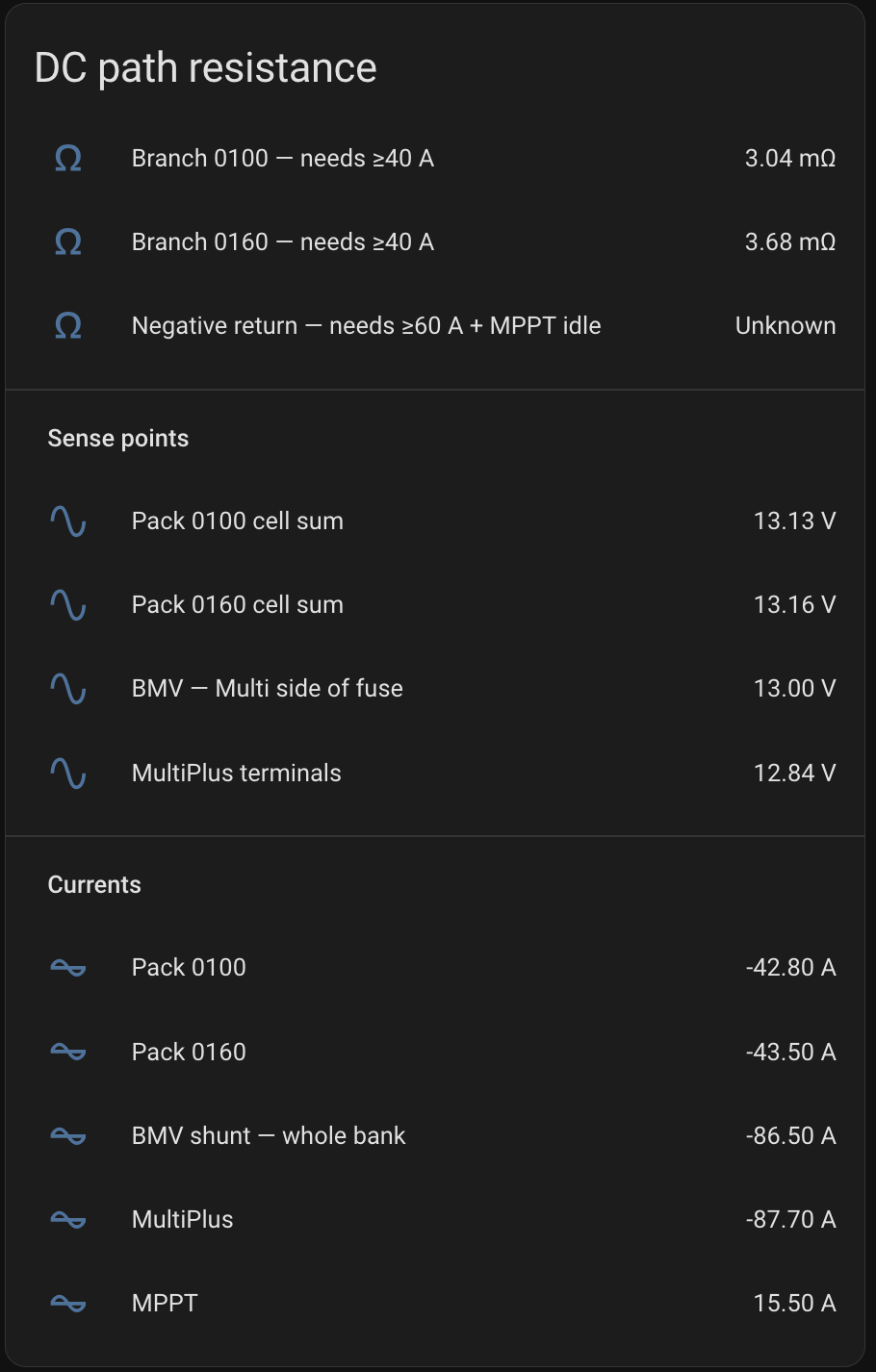
A bigger bank would never have fixed that. It is worth ruling out before spending money on batteries — the full story is in the power section of the main page.
Still Open
Not finished
Charge current limits and the absorption taper
The two packs do not always share the load evenly, and the tail end of the absorption cycle still needs tuning. This is a live project rather than a finished one, which is worth saying plainly — most writeups stop at the point where the thing switches on.
Questions about any of it? Get in touch — or head back to the main RV Tech page for the monitoring side.
Built with Claude Code.